The operating principle of a single-jet, dry-running impeller meter
for drinking water
Operating principle and design of a single-jet, dry-running impeller meter for drinking water
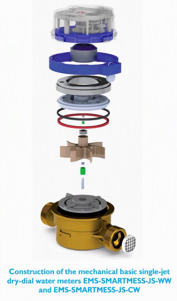
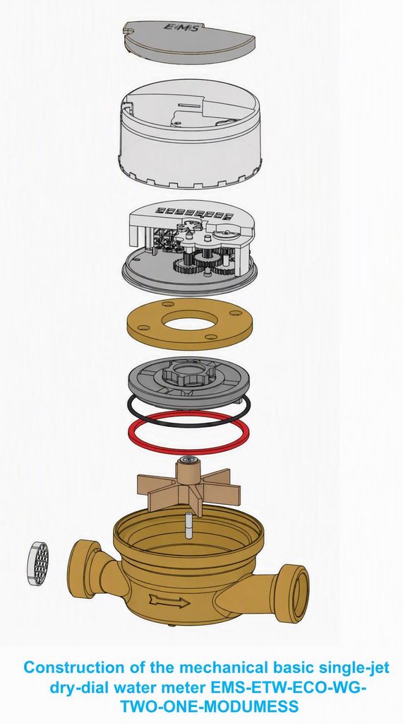
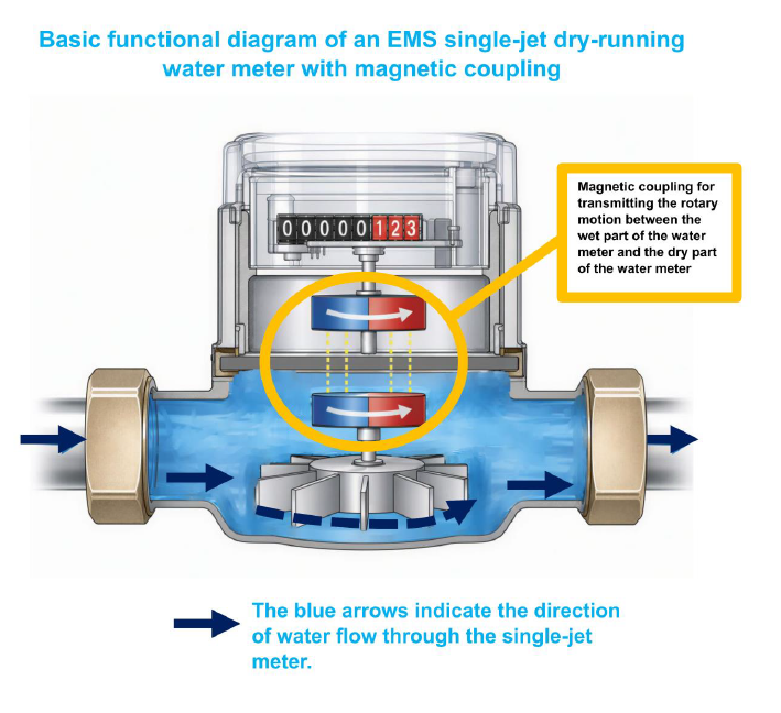
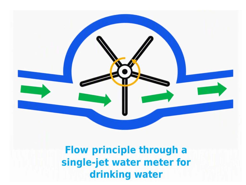
In a single-jet, dry-running impeller meter, the impeller is driven by a single jet of water. This jet enters the measuring chamber through the bore in the inlet of the meter housing and strikes the impeller tangentially, i.e., laterally at its circumference. This tangential flow generates a torque that sets the impeller in rotation. The rotational movement of the impeller is then transferred to the counter. In this way, the amount of water flowing through the meter can be measured and displayed. The fundamental measuring principle is therefore the conversion of the water’s flow energy into a controlled rotational movement of the impeller.
Significance of the dam ribs
In a single-jet impeller flow meter, the impeller’s rotational speed is not directly proportional to the actual flow rate without additional design modifications. This is due to the changing forces and moments acting on the impeller. To compensate for this, single-jet impeller flow meters are equipped with baffles. These are typically located above and below the impeller. They selectively influence
the flow and generate additional braking forces or moments. Together with the impeller, the baffles act as a vortex brake. They ensure that the impeller’s rotation is controlled and stabilized at varying flow rates.
Through the interplay of:
- the tangentially entering single jet
- the rotating impeller
- the buoyancy ribs arranged above and below
- the braking moments generated by the design
a very good adaptation of the impeller speed to the actual flow rate is achieved.
The forces remaining after the mutual action of the drive torque and the braking torque essentially only need to overcome the frictional forces of the bearings and the moving components. These frictional forces are approximately linear to the flow rate. This results in a suitable and reproducible relationship between water flow rate and impeller speed for the measurement task.
Load on the impeller bearing
Compared to a multi-jet impeller meter, the impeller bearing in a single-jet meter is subjected to a greater one-sided load. In a multi-jet meter, the impeller is struck by several water jets, allowing the forces to be distributed more evenly.
In contrast, in a single-jet meter, the water jet hits the impeller from one side only. The resulting forces and moments push the impeller laterally. This lateral load also acts on the impeller bearing.
Such one-sided stress can generally lead to increased wear of the bearing components. This can affect the service life of a single-jet impeller meter compared to a multi-jet meter.
However, with modern bearing designs that meet current technological standards, critical wear within the calibration validity period is not normally expected. This also applies to meters that have the corresponding type approval. The bearing is designed to withstand the forces occurring in the intended operating range and to ensure the required measurement accuracy during the relevant operating period.
Use as a Residential Water Meter
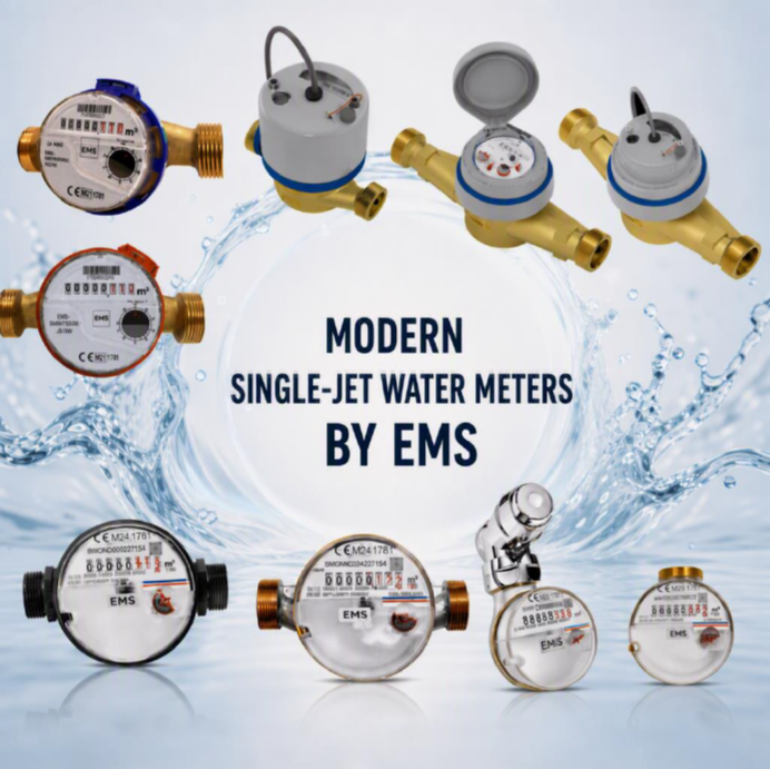
Single-jet impeller meters are frequently used as residential water meters. For this application, they are available in sizes Q3 1.5 and Q3 2.5, among others.
The selection of the meter size depends on the requirements of the specific installation. In particular, the expected flow rate, the pipe dimensions, and the technical specifications of the water supply system must be considered.
Traditionally, single-jet impeller meters are equipped with mechanical counters in a dry-running design. In this design, the counter is located outside the water-carrying
area. The rotational movement of the impeller is transmitted to the counter via a suitable linkage, while the display remains dry and easily readable.
Electronic meters are increasingly being used. These offer additional options for displaying, storing, and transmitting consumption data. Depending on the model, electronic meters can be equipped for features such as digital display, wireless transmission, or integration into higher-level reading systems.
Meter Adjustment
The adjustment of a single-jet impeller meter is normally performed via the pressure plate, which is equipped with baffles and located above the impeller.
For adjustment, the pressure plate is rotated. This allows the flow in the measuring chamber to be precisely controlled. The position of the baffles alters the braking forces acting on the impeller, thus enabling precise adjustment of the metering characteristics.
This adjustment is carried out with the meter mechanism removed or not yet installed. This ensures access to the pressure plate and allows the adjustment to be performed under controlled conditions.
After the adjustment is complete, the meter mechanism is reinstalled. The meter is then ready for its intended installation and consumption measurement.
Standard Design as an Inline Meter
The standard design of the single-jet impeller meter is the inline type. In this design, the complete meter is installed directly into the pipeline. Water enters the meter on one side, flows through the measuring chamber, and then exits on the opposite side.
As previously described, the inlet and outlet channels of the measuring mechanism in the inline type are formed by bores in the connection fitting of the meter housing. These bores guide the water into the measuring chamber and then back out of the meter.
The internal diameter of the bores corresponds approximately to the nominal diameter of the respective pipeline. This allows the meter to be seamlessly integrated
into the existing installation. The flow path is designed so that the water flow is directed precisely into the measuring chamber and the single jet flows onto the impeller according to the intended measuring principle.
Installation and Replacement
With the inline type, the complete meter is installed as part of the pipeline. The connection fittings are connected to the corresponding pipe connections and form the inlet and outlet of the meter.
When replacing a meter, the entire meter is typically removed from the pipeline and replaced with a suitable new one. This allows the housing, measuring mechanism, impeller bearing, and register to be replaced as a single unit.
The inline design offers a clear and compact solution for installations where the meter is to be integrated directly into the pipeline. It is particularly suitable for decentralized consumption metering, for example, in apartments, individual units, or similar water installations.